
|
|
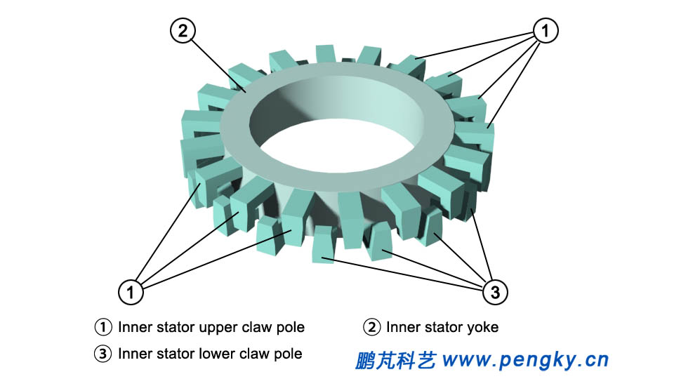
This section will introduce another basic form of transverse magnetic flux permanent magnet generator, this model structure is somewhat similar to a claw pole generator, and there are indeed many similarities, however, transverse magnetic flux in the claw-pole generator rotor produces a multi-pole magnetic field, it is still a radial air-gap magnetic flux from the power generation theorem. The transverse magnetic flux permanent magnet generator described in this section is an outer rotor structure, and the inner stator adopts a claw pole structure, seeing in figure 1 below. |
|
 |
|
| Figure 1 Inner stator of transverse flux generator | |
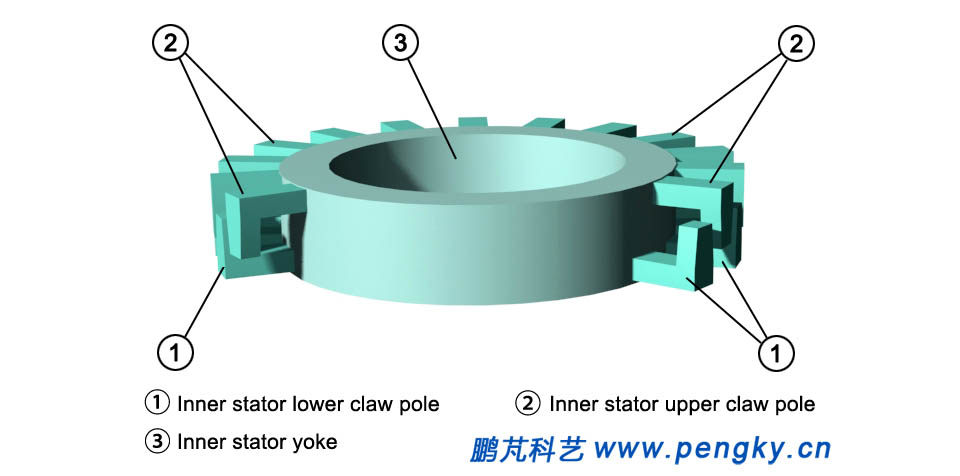
A plurality of L-shaped claw poles are vertically and symmetrically staggered and installed on the outer circumference of the stator yoke, showing in figure 2 In order to see the claw structure clearly, the front part of the claw is hidden in the figure 2. |
|
 |
|
| Figure 2 Inner stator of transverse flux generator | |
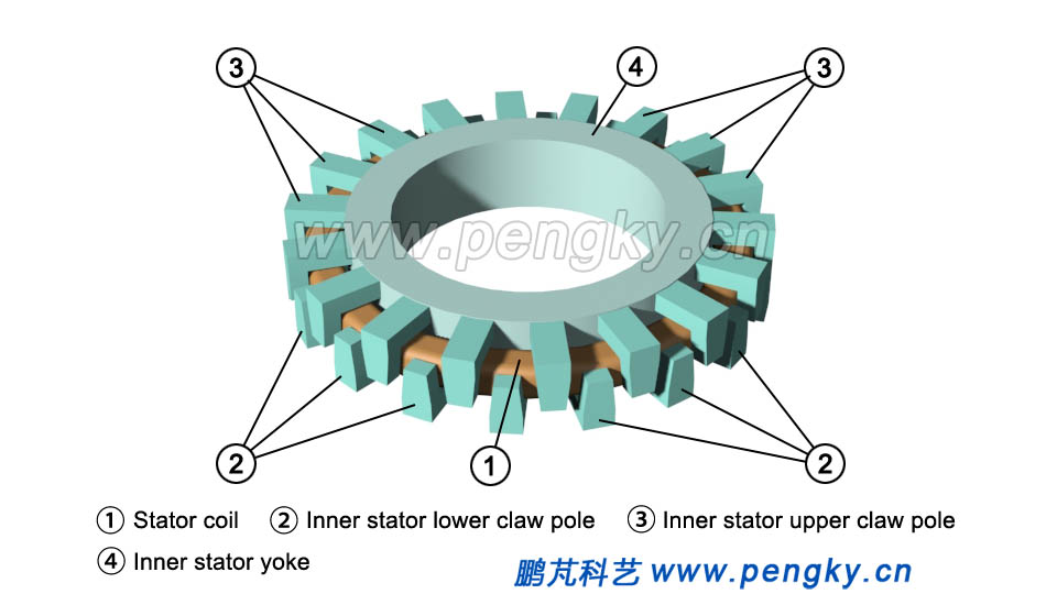
The annular coil winding is installed in the middle of the upper and lower claw poles of the stator to form an inner stator, seeing figure 3 below. |
|
 |
|
| Figure 3 Inner stator and coil windings in a transverse flux generator | |
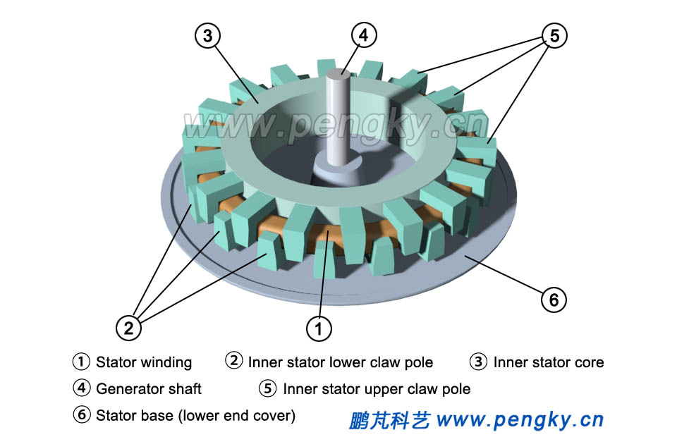
The inner stator is mounted on the stator base, and the stator base is still the back terminal cover of generator. There is a generator rotation shaft in the middle of the base, seeing figure 4. |
|
 |
|
| Figure 4 Inner stator and base in transverse magnetic flux generator | |
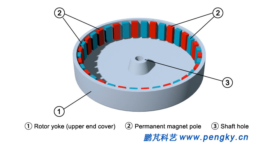
The magnetic poles of the generator rotor are composed of a plurality of permanent magnets, and the rotor yoke is the upper terminal cover, each permanent magnet pole is mounted on the inner surface of the yoke, seeing figure 5 (the bottom is placed up). The magnetic flux direction is radial, the magnetic flux of the adjacent magnetic poles is opposite in the direction, and the total number of magnetic poles is the same as the number of poles of the stator claws,? both are pair numbers. |
|
 |
|
| Figure 5 transverse flux machine outer rotor | |
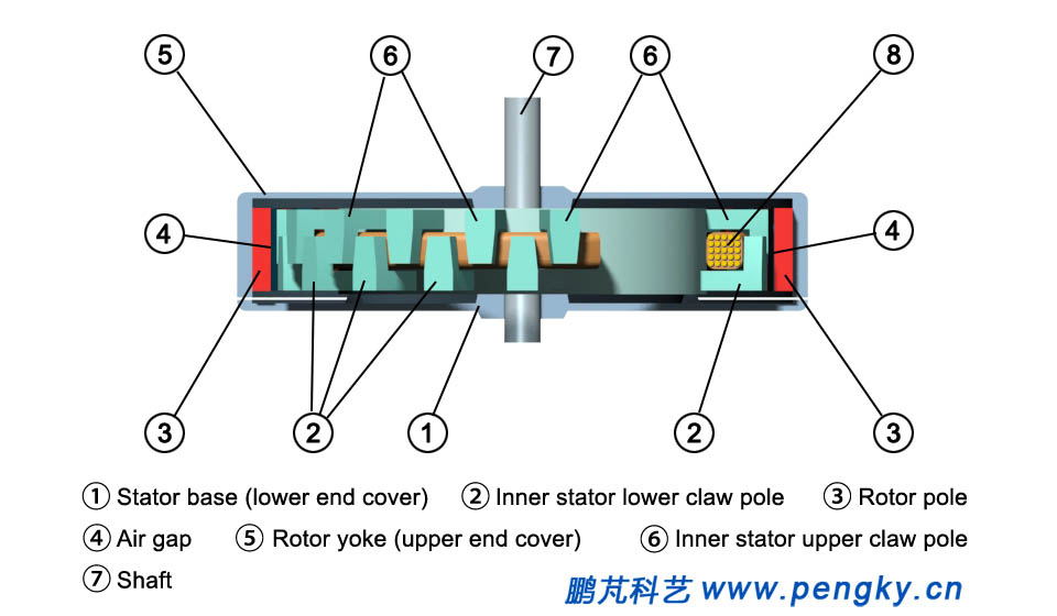
Insert the outer rotor into the stator shaft, there is an air gap between the stator claw pole and the rotor pole. The rotor can rotate freely, the magnetic flux direction of the air gap is radial, seeing figure 6. In order to clearly see the structure, several claw poles are hidden on the right side of the stator, the winding is cut off for a while in the figure 6 below. |
|
 |
|
| Figure 6 Cross-sectional drawn of transverse flux machine | |
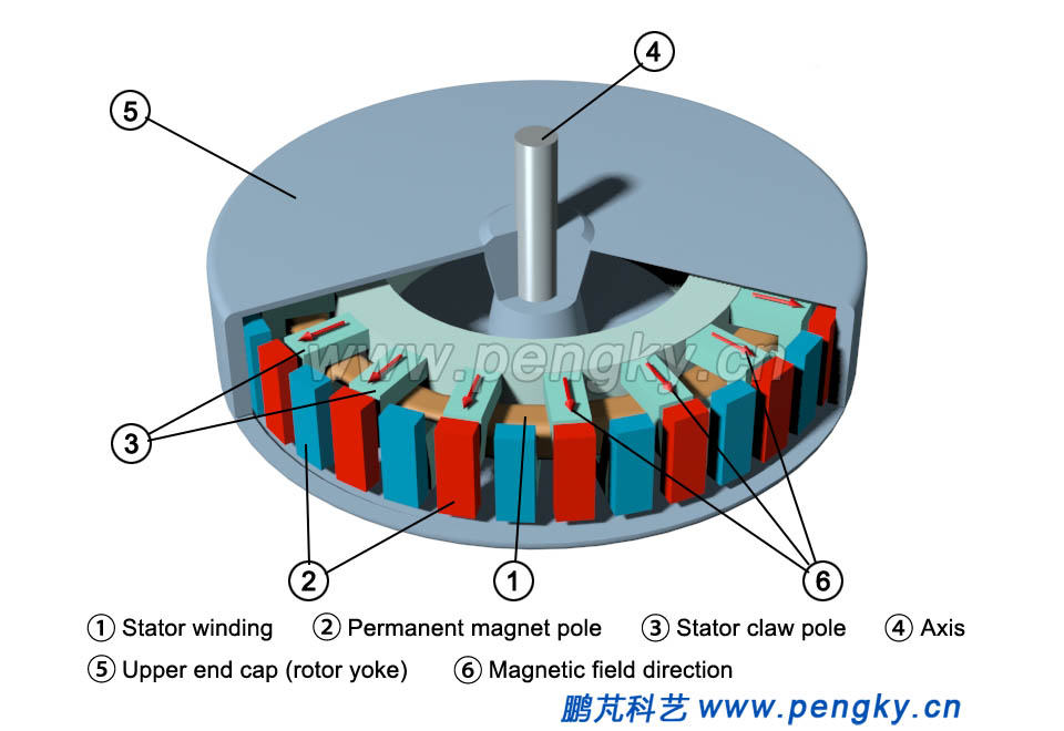
In figure7, set the red permanent magnet flux direction outward, and the blue permanent magnet flux direction to the center. all the red magnetic poles are aligned with the upper claw poles of the stator, and all the blue magnetic poles are aligned with the lower claw poles of the stator. At this moment, the magnetic field lines pass from the blue magnetic pole through the air gap to the lower claw poles, pass the stator yoke to the upper claw poles, pass the air gap to the red magnetic poles, and return to the blue magnetic poles through the rotor yoke. The lines of magnetic force form a loop around the stator coils, the direction of the magnetic lines of force for all the poles and the claw poles are the same. |
|
 |
|
| Figure 7 Solid cross-section drawn of transverse flux generator (1) | |
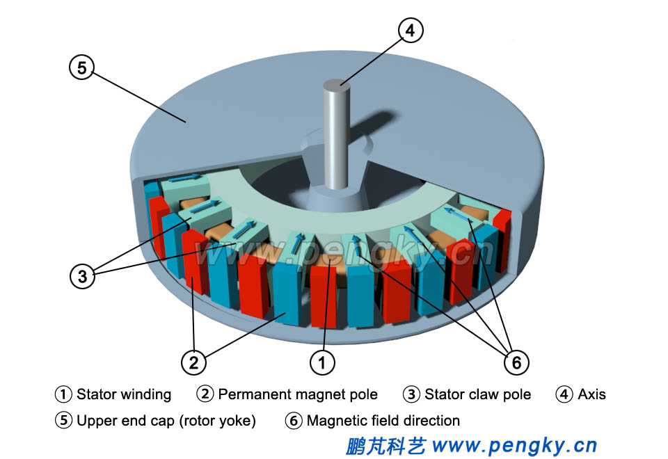
When the rotor turns clockwise by a magnetic pole angle, all red poles are aligned with the lower claw poles of the stator, and all blue poles are aligned with the upper claw poles of the stator, see figure 8. At this time, the magnetic field lines pass from the blue magnetic poles through the air gap to the lower claw poles, pass the stator yoke to the upper claw poles, pass the air gap to the red magnetic poles, and return to the blue magnetic poles through the rotor yoke. The lines of magnetic force form a loop around the stator coils, the direction of the magnetic lines of force for all the magnetic poles and the claw poles are the same. The direction of the wrap is opposite to that of figure 7. |
|
 |
|
| Figure 8 Solid cross-section drawn of transverse flux generator (2) | |
Each time the rotor rotates by one pole angle, the direction of the magnetic flux around the stator coil is reversed once. When the rotor rotates continuously, the stator coil induces an alternating current. The different from the claw pole generator is that the claw pole of the claw pole generator is used as the magnetic pole of the rotor, but the magnetic flux direction of the claw pole is constant, and the claw pole can be made by ordinary soft iron. In this case, the magnetic flux in the claw pole is repeatedly flipped and must be made of silicon steel sheets to reduce eddy current loss, the stator yoke is also the same, so the fabrication is much more complicated. |
|
| Back to Previous Page |
